
The amount of grief I’ve put up with to get this working buggers imagination.
To have a NTP stratum 1 server, you need to have a certain set of capabilities.
First, you need a stratum 0 device. This is an atomic clock or a GPS receiver.
You need a method to communicate with the GPS receiver.
Your clock needs to be network connected.
Each of these pieces must be done correctly with the least amount of jitter possible.
Jitter is how much a signal deviates from its target. If the jitter is zero, then we have a level of accuracy that depends solely on our reference clock.
The little GPS unit is self-contained. If it is supplied 3.3V of power, it will search for satellites and do the calculations to know what time it is and where it is.
The calculations turn out to be for someplace along the cable from the antenna to the GPS unit. Some highly accurate versions of the GPS SoC measure the length of the antenna feed and account for that in the calculations. Regardless, it is the time for a place a little offset from the actual GPS chip.
For me, that is a delay of around 10ns.
The GPS will communicate via a serial protocol. This means that we have a delay from when the message is received and when we can put our timestamp on the message. For me, that is around 140ms.
This can be discovered by tracking the time indicated by the serial GPS and the system/local clock. The local clock is synced to multiple remote NTP servers to get this number.
Unfortunately, there is about a 1ms jitter in this signal.
If I were to use a USB converter. I.e., serial to USB, that jitter goes up. I am seeing a jitter of 4 to 9 ms.
Using the serial directly is a good start.
But there is another signal that can help. That is the Pulse Per Second (PPS). We are using a 1second pulse.
IFF we can capture the time at which the pulse arrives, we can get a very accurate start of the second marker.
This requires that the hardware have a general purpose input/output(GPIO) pin available.
Most motherboards do not have exposed GPIO pins. Worse, some boards have GPIO pins, but there is no documentation on how to access them.
So the server board requires GPIO plus a method of accessing those pins.
There are two ways to discover a change of value, we can pole for it, or we can get an interrupt.
Consider you have your phone alerts silenced so you don’t get a noise every time you receive an email or message.
You have to check your phone for new messages. This is “poling”.
If somebody calls, your phone still rings. You then immediately check to see who it is and perhaps answer the phone.
This is an interrupt.
The default operation of a GPIO pin is poling driven. Even if it is generating an interrupt, that interrupt is only used to record the change of value.
What is needed is a high-performance interrupt handler. When an interrupt happens, the handler records the system clock. A user land process watches, either poling or interrupt, it doesn’t matter, for that value to change.
When it changes, the software knows that the GPS “knew” it was the start of the second when it created the pulse.
The amount of jitter is only as much time as it takes for the system to allocate a CPU and for that CPU to process the interrupt. In other words, really, really fast.
Currently, the jitter on my PPS reference clock is 300ns. Because of the many samples that have been taken, the PPS reference clock is currently running 17ns from the real time. That has been going down over the last few hours. By the time you read this, it is likely to be even less.
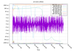
The PPS clock is so tight that the other clock sources hide the values, even in logarithmic form

This is an interesting graph, to me, as it indicates how the system clock is slowly being conditioned to keep more accurate time. It software currently says that the drift is -17.796271 ppm off which I think translates to 3.324ms
So how bad was this task? More painful than I wanted it to be.
I’m fine with “dumb” computers. I started programming on 6502s. I’ve been bit slinging for 50 years. Programming Arduino’s? No problem.
Building a PC from components, installing any compatible operating system? I do it a dozen times a week when developing.
The Raspberry Pi is a different animal. It isn’t sold as a low-level system. You can use it that way, but that is not how it is intended to be used. It is sold as a System On a Board (SOB) that runs a modern (Linux, Android) operating system.
This is where things get strange. When we are working with modern PCs, they have known hardware. We boot the computer, run the OS, the OS has drivers to talk to the hardware. Everything just works.
This is possible because PC’s have a Basic Input Output System (BIOS). This is a low-level set of routines that are there to allow accessing certain parts of the hardware with a standard Application Protocol Interface (API).
Since every BIOS has the same API, OS vendors can use the BIOS to load enough of their software to continue booting. The hardware is attached in known ways. The hardware vendor supplies the drivers for their hardware. Linux people write their drivers if needed.
So consider that SOB. It has a serial port. The serial port is controlled by a standard UART. That UART is programmed in a standard way. They are all the same.
In order for that UART to work, the software needs to know where the UART is located in memory (or on the I/O bus). In addition, the pins that the UART uses have to be configured for the UART. Most UART’s use standard pins on the GPIO header. The pins that the UART uses can be used in different modes for different things.
The problem comes from that address being different in every SOB or SOC. A board could have one, two, or more GPIO driver chips. It all depends on the designer.
The developers overcome this issue with what is called a “Device Tree”.
The device tree is a parsable description of devices and their locations in memory or on the I/O bus.
The board I purchased doesn’t have a supported modern OS. The only OS that I could get to boot was released in 2016. The OS is not really supported anymore. The board itself was flaky. It would randomly reboot, or just power off.
The “modern” OS that should have worked didn’t even complete the boot.
In discussions with a community support person, we decided that there was hardware that was not being properly initialized in the kernel. I.e., we had a bad Device Tree.
The replacement Banana Pi doesn’t have a supported modern OS. It is fully supported by Arabian, which is a supported, modern OS.
When I first booted the system, it just worked. I was thrilled. It has continued to work properly.
Then I plugged the GPS in. I could see it blinking. This indicates that it has a lock and the PPS signal is being sent.
But I can’t get any input on the serial ports.
It turns out that the default device tree doesn’t activate that UART. Once I figured that out, I had to find an overlay to the device tree to turn on the UART.
That was a pain, but it happened.
Working serial, no PPS.
With the tools on hand, I could monitor the GPIO pin and see the PPS. But it wasn’t doing anything.
I loaded the correct kernel modules, still no PPS.
My Google Foo suggested that the device tree entry for PPS was missing.
Yep, there was no PPS overlay.
The Linux kernel documentation describes the Device Tree. But no real examples, and nothing fully commented.
By comparing multiple sources, I finally was able to create a device tree overlay for PPS. I need to figure out how to return that DTD to the community. The problem is, I don’t know what the hell I did. I made it work. I think I know what was done. Nonetheless, it was truly a case of looking at different device tree overlays and picking out the parts that seemed to match what I needed to do.
I don’t think I’ve had this much difficulty hooking up a piece of hardware since 1983, when I was attempting to attach a DEC 10 MB hard drive to a computer that wasn’t really a DEC.
The only tasks remaining is to put everything in a case and move it to its long-term home, off the top of my computer.
I didn’t realize you had so much trouble.
I went through all this on a BeagleBone Black, which also has the “device tree” magic. I got it working fairly quickly. Unfortunately I no longer have any of that because the board just went dead one day, it won’t even attempt to power up anymore.
My new NTP server is a Raspberry Pico, which is pretty nearly “bare metal”, no “modern OS”. I have it working nicely with its WiFi interface, and nearly so with an 10 Mb/s Ethernet board that uses an ENC28J60 chip. Surprisingly, the 10 Mb/s Ethernet has substantially better performance (lower latency) than the WiFi.
At some point I’ll come up with a PCB and schematic and published code for this.
I have a small understanding of latency, bandwidth, and jitter. Wi-Fi is known to have worse jitter than a wired connection.
While many of the smaller boards do allow you to connect an Ethernet hat for wired connectivity, often those interfaces are not particularly fast nor are the consistent. I.e., they have too much jitter.
Finally, I have started moving to Fiber. With that has come some limitations on older technology. In particular, some ports I currently have open do not support 10/100 Ethernet. The slowest they support is 1Gbit.
This required the board with built-in Ethernet at 1Gbit, functional GPIO, and functional UART.
“ The amount of grief I’ve put up with to get this working buggers imagination.”
I was going to suggest that perhaps you meant to say ‘beggars’ imagination but after reading that I think you chose the right word after all.
Wow, that was a nightmare.