
A few years ago, NASA crashed a Mars probe into the surface of the red planet when they got their units mixed up. One group was using metric, and the other was using Freedom Units.
I would have laughed if it hadn’t been such an expensive mistake, both in terms of money and lost opportunity.
I’m a firm believer in Freedom Units. It is what I use regularly. My last big learning curve was going from 1/2 inch, 1/4 inch, 1/8 inch to 0.500, 0.250, 0.125, and 0.062, as in thousandths of an inch.
This small-scale metric stuff is for the birds.
Whenever I start to get a bit confused, I go 25.4 mm == 1 in. That’s close enough to 1/32 of an inch that I can use it for a working number.
The other number I use is 6 mm, which is around 1/4 inch. These are just to get some sort of feel for the numbers.
I just printed my second book for crimpers and terminals. It is 5 x 3 units and 6U tall. I found a Gridfinity bin to hold the crimpers I purchased. All’s good.
Except the bin doesn’t fit the pair I purchased. Slightly different.
So I went back to learning how to do this.
To help with just this task, I purchased a cutting mat with grid lines and other fancies on it. Here is the first photo I took.
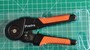
It is in its blow-molded holder. This should give me the ability to trace the factory’s cutout/shadow box.
Once this is imported into FreeCAD, you rotate it until the grid is aligned properly, then you “calibrate” the image.
Calibrating means drawing a line between two points with known distance. In this case I have a bunch of 1cm squares. To average out my error, I clicked on one intersection, then counted over 70 mm by 10 mm and clicked. The image scaled. It is now ready to be traced.
I used a B-spline curve, which worked well. I’m getting the hang of it again, it having been 20 years since I used b-splines of this style.
When done, I simply cut the curve from a rectangle, padded the result to 3 mm, and printed it. This allows me to test fit the tool to the shadow without wasting lots of plastic and time.
It didn’t fit. It was too small.
I need to do it over again. This time I’m omitting the blow mold and working directly from the tool. I’ll draw a close-fitting curve, then pad it in X and Y by a mm or so.
This will work better; can you see why?
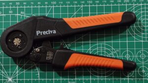
Yep, one side of the cutting map is in Freedom Units and the other in metric. My first photo was on the Freedom Unit side because it is less crowded. When I was counting out 70 mm, I was really counting out 3.5 in. If I had input 3.5 in into the calibration, it would have been fine.
Leason learned.
This reminded me of the “Stonehenge” malfunction in “This Is Spinal Tap”. Great movie.
Geography is hard… (OK, that sounds funnier when you realize I meant geometry…)
.
It is all part of the learning curve. Tolerances can be a bear. They can be even doubly troublesome when you are using mixed units. Light travels exactly how many furlongs in a fortnight?
.
Post pics when you get this one completed. This is exactly the type of thing I am looking to create. A single “book” that has the tool, and supplies all organized.