
Small Engines and Boilers
A Manual
Concise and Specific Directions For the Construction of Small Steam Engines and Boilers of Modern Types
Copyright 1899
Wow, isn’t that a mouthful.
Preface
The intention of the author in writing this work has been to furnish specific directions and correct dimensioned plans for small engines and boilers, used either for pleasure or power purposes, in lieu of sketches and gossip about such machines. It has been assumed that those who need a guide of this kind have some acquaintance with ordinary machine work, and the usual facilities for it, if even but a small lathe and a vice-bench; with this outfit a great deal may be done.
The boilers shown will do a great deal of work for their superficial dimensions, if properly managed. They have ample grates and heating surfaces, and will maintain a steady evaporation continuously with good fuel and management. The work also contains hints upon lathe-work, vice-work, and finishing metals, which it is believed will be of service to those who have had but a limited experience.
High expansion engines have not been treated, for the reason that they are beyond the mechanical and engineering experience of the majority of persons who will purchase a work of this character.
I have been known to use polysyllabic words when a monosyllabic word would work just as well. This guy writes at an entirely different level.
Here is the gist of it: This stuff used to be simple and well known. It wasn’t uncommon to have regular people just make a steam engine in their barn.
He talks about how easy it is to make some of these things, until you find that he strongly suggests that you have patterns and castings made by a good quality foundry and pattern shop. It is better to pay 10 cents per pound for your castings, knowing them to be good, than to pay 6 cents and struggle.
I know how hard it is to make good patterns. I’m horrible at it but am willing to try again; now that I am better at hand woodworking, it makes a difference.
So I did some looking around. Did you know that you can still hire people to make patterns? Or you can just 3D print them, and I don’t mean the 3D printers in your house; these printers are designed to make foundry-ready patterns.
I’m not looking for an iron foundry near me to cast the patterns. I could do it myself in aluminum, and I want to try iron, but I’m unsure of myself at this point. I still might give it a go.
One thing I do know is that the shrinkage between aluminum and iron is different, so I can’t use the same pattern for both unless I design for it.
On the other hand, it might be nice to be able to have a place where I can get castings done.
Back to the book
This is the third major attempt I’ve made to read this book. I realized today why I was having so much difficulty. I am not used to illustrations being fully dependent on the text.
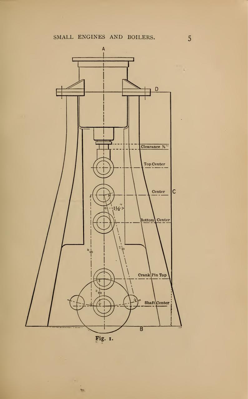
This is a perfect example of what I’m talking about. This looks like a mechanical drawing, something to build a model from. It isn’t. It is a “skeleton diagram”. I think I got the term correct.
What this shows is the relationship between the different parts of the engine so that you can know how big it needs to be.
The figure shows the cylinder, frame, cylinder brackets, packing gland, packing nut, piston rod, theoretical cross slide, connecting rod, and theoretical crank. Oh, and the base plate.
The connecting rod is 3 times the length of the stroke. The diameter the crankpin travels is the stroke of the piston, so 2 inches. From the length of the connecting rod, the location of the crank at center of the cylinder, it is possible to determine the clearance needed for the connecting arm.
But the words aren’t what I expect; the top double circle is labeled “Top Center”. Today we would call this Top Dead Center (TDC). Likewise, “bottom center” is Bottom Dead Center (BDC), which we use for timing car engines today.
I studied this figure for hours and never did figure it out. There aren’t enough dimensions to make anything from this.
That’s because it isn’t a drawing to make things from; it is a diagram to help you with your design of an engine.
And this is why it is so hard. This is a mechanical drawing that was well within the ability of the target audience of this book to read and understand. Yet it would be nearly impossible for someone with the same knowledge base to use it as is today.
First, we don’t draw objects this way. It is missing views.
This would have been drawn with at least a top and side view as well as from both ends. The cross section would have been indicated with a cut line in one of the other views. Instead, all of that information is buried in this one figure and maybe something in the text.
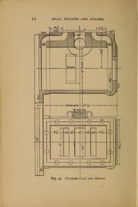
The bore of this is defined as 3 inches, and the depth of the bore is 5 11/16 – 5/16 or 5 3/8 deep. But that is not called out. From this diagram, today, we would assume that the critical dimension is the 5/16 thickness of the rear wall. We can guess that the front flange is also 5/16, but there is no callout for that.
And while the steam passage is called out to have a 3/8 diameter, the distance from the steam passage to the front face is not defined. We also have radii that are not defined. This being left to the workman.
I made it most of the way through the book today. I need to go back over a couple of the paragraphs. The important thing for me was to stop focusing on the figures and instead to focus on the text.
Go ahead and enjoy some light reading:Small Engines and Boilers
Um, on that first illustration, i read the stroke to connecting rod length as 1:2, not 1:3. The crankshaft center to pin is 2″, which is a radius, so the distance between the pin at TDC and BDC, or stroke, is 4″. The conrod shaft length called out as 8″.
.
To be more helpful, these dims, and the dims for the housing, would be called out as variables and the clearance needed would be expressed in those terms. That’s a more general case but if the reader knows a little trigonometry, it’s arguably more broadly useful. Anyway, yes. They don’t often write books like that these days.
You are correct. It is a 4 inch throw. One of the issues I’m having is that I’m working with a number of old school drawings where sometimes they use diameter and sometime radius and I missed that this measurement was a radius and not a diameter. The 3X I pulled from memory from the text. This engine is only 2x. I don’t understand why. I’ll have to read more.
As a degreed and experienced drafter, those ARE proper mechanical drawings. What they are not is shop drawings for manufacturing. They are simply used as examples for a single concept. You’re supposed to produce the shop drawings based on the information provided.
As a novice, self taught machinist, my hat is off to you. I’m doing my best and your comment is actually helpful. Of course it opens up another rabbit hole.
If you could please provide a reference to a textbook that you think might be helpful to me in reading and understanding mechanical drawings, I would be most greatful.
I actually can’t recommend a book for a couple reasons, one: I started over 25 years ago and can’t remember what I used back then…🤣 two: as much as it pains me because knowing how to hand draw really does make for a better end result, learning that skill today is a waste of time as 3d packages have become so good, and easy to learn and even inexpensive that starting in 3d is actually better today. It takes a certain kind of brain to translate flat drawings into a working model in your head, you either have it or you don’t. But a modern CAD package will produce that working model for you and show where you screwed up long before you cut metal. I’d suggest Fusion360 as it has a free hobbiest tier that is pretty damn powerful.