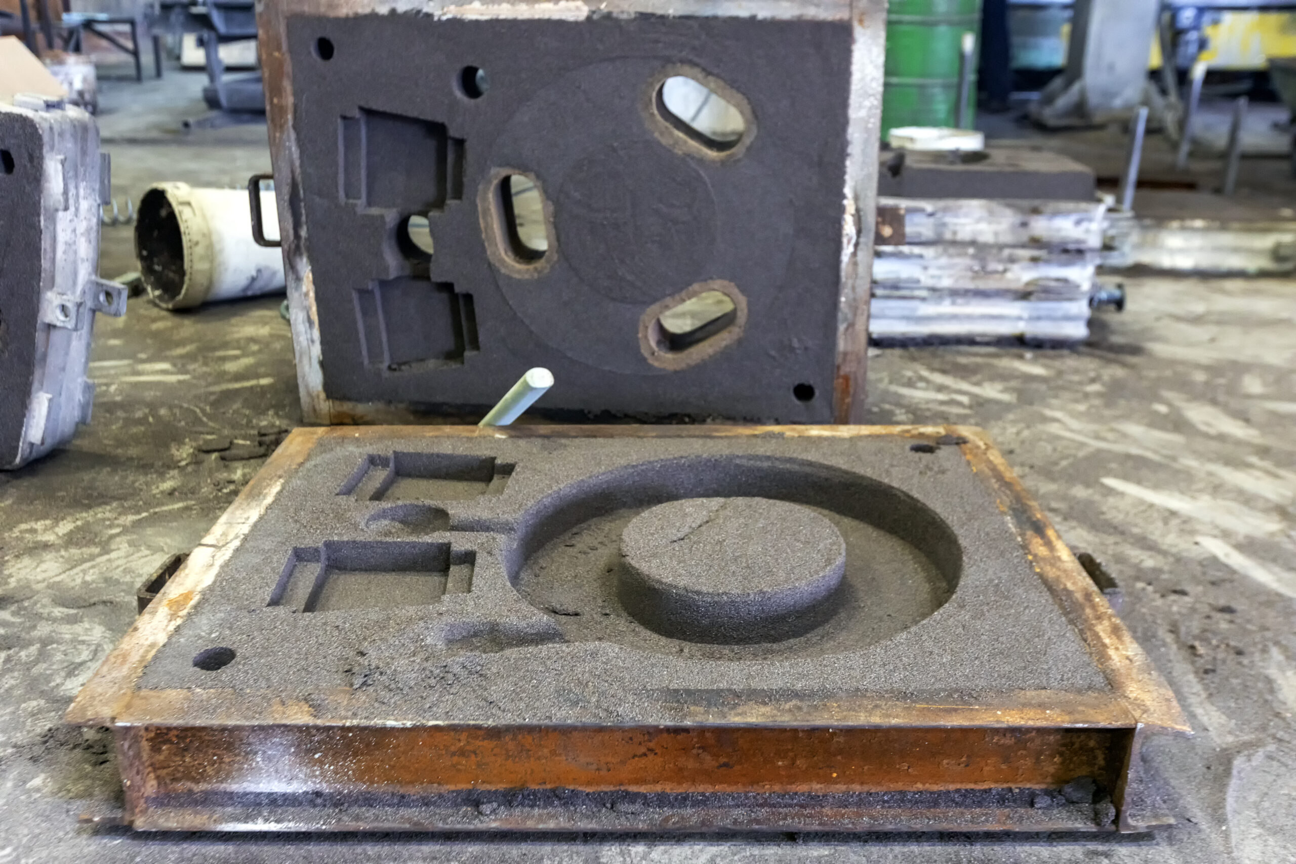
3D-Printing

Making Flasks

A flask is the technical name for the open top and bottom used to contain sand for sand molds.

The concept is simple: make a pattern of the thing you want to cast, surround it with hard packed sand, remove the pattern, fill the void with molten metal, wait for it to cool, remove the solid metal from the sand, reuse the sand.

There are three main skill sets in this process: the pattern maker, the rammer, and the person making the pour. If any of them messes up, you are likely to end up with a bad casting.

Pattern making is the most difficult part, in my mind. You have to design a pattern that can withstand the stress of being in sand that is being hammered. It needs to be designed so that it can be pulled from the sand mold without breaking the mold. This means no undercuts, a smooth surface, and taper to the sides.

In addition, metal expands as it is heated and shrinks as it cools. This shrinkage needs to be allowed for in the patterns. Different metals shrink at different rates and require different scaling in the patterns. In other words, a pattern designed for cast iron will be to small when cast in aluminum.

Because of the violence of the ramming process, the flask has to be rammed up on a solid surface. Because there is a lot of sand that needs to be recovered from the ramming process, the ramming table, called the molding table, has to have catch basins to catch the excess sand.

We also have to be able to flip the flasks, cut patterns in the sand for gates and runners, and do a bunch of other things.

The flask also needs to be sturdy enough to withstand the ramming up process. If the flask flexes under impact or vibrates, or the inside surfaces are to smooth, the sand will fall out or not compact enough.

Thus, we want to have strong, solid flasks.

Each flask is constructed of two parts, the cope and the drag. The true difference between them is one has alignment pins, and the other has alignment holes. This is so the cope can be put back in the same place when it is put back on the drag after removing the pattern.

The cope and the drag are each made of four sides. Two sides have lifting handles and the alignment hardware. The other two sides do not.

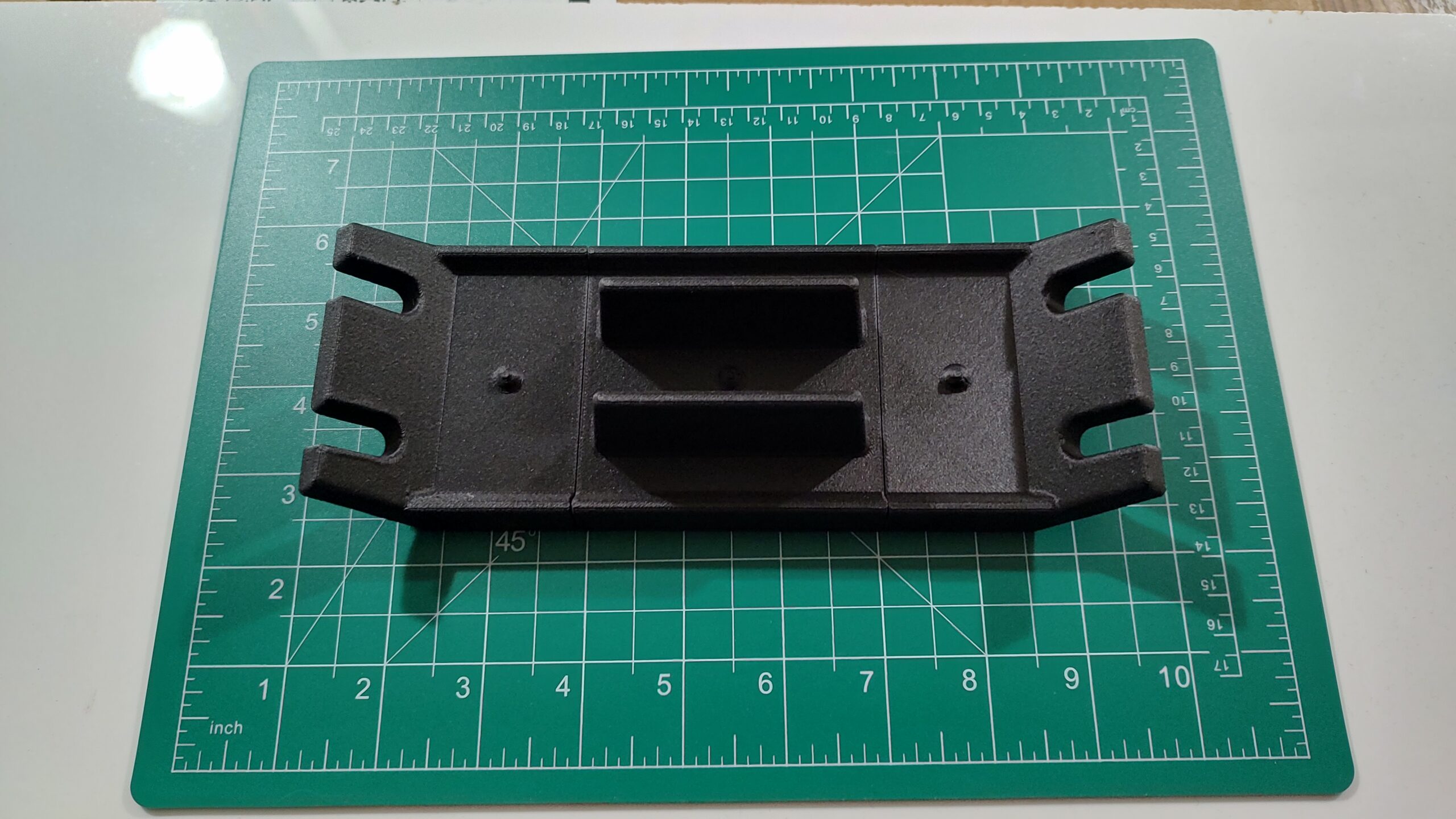
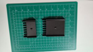
This is an end side. The two edges that are coming up will have holes drilled in them to hold a pin or to take a pin. It takes two of these for the cope and two for the drag.

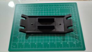
This is what it will look like when we are using it; the slotted ears on the ends will bolt to the sides of the flask parts.

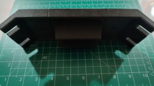
This is the side the sand will be rammed into. The back side features grooves to help support the sand when it is rammed up.

The piece shown here is the smallest end piece I can foresee using. It is about 6 inches long. To make the side longer, you add extension pieces like the following.

These are 40mm and 80mm wide, or 1.5″ and 3″ long. The handle section is also 3″ long. This means I can create a flask side of almost any length in 1.5 in units.

So, to make one complete flask, I need eight sides. That means that the ear pieces will be rammed up 8 times. The handle pieces will be rammed up 4 times. Any extensions will be rammed up 8 times.

I want more than one flask, this means these patterns will need to be used over and over again. That requirement means I want these to be as strong as possible.

Also, they connect with pins and slots. Those are weak points, I want those to be strong as well.

PA6-CF gives me all of that.

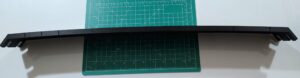
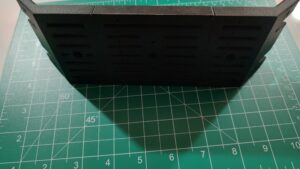
Here is the longest side I can make currently.

One of the issues with snapping pieces together is that you don’t get perfect alignment. As you can see, the side has a major curve in it. I can take this out by carefully sanding and touching up the mating surfaces. This will make the side flat; it just takes time.

Instead, I’m going to drill holes through my molding board to attach the pattern to. This allows me to flatten the pattern.

My hope is to have enough sides to have 5 to 10 flasks available to me. Since the sides just bolt together, I expect I will be able to mix and matcch the sides after I surface the top and bottom edge flat and to specification.

Could I have done this all in low cost PLA? Yes. And it likely would have held up great. And it would have been cheaper. I could have printed it in PETG which is stronger still, or ABS, or ASA, both strong contenders. The fact that I could use PA6-CF was more of the sell than any actual engineering calculations.

The final results of the print are wonderful. I’m looking forward to casting weather.

View of the sand mold for steel casting. Sand casting, also known as sand molded casting, is a metal casting process characterized by using sand as the mold material.

Foundry Patterns

Yesterday, the circle of interests completed a circuit.

One of the primary reasons I purchased a 3D printer was to make foundry patterns. I know how to make patterns, I don’t have the skills I need to make patterns.

Many in the small scale casting arena are turning to 3D printed patterns.

These have the advantage of going directly from CAD to pattern.

They have the disadvantage of needing more prep work.

When you ram up a flask, you are forcing sand with a binder to be compacted so tightly that it will stick to itself. “Greensand” is made from sand, southern bentonite, and water. You need add enough water to cause the clay to bind. That water needs to be mixed in a process called mulling. If you add too much water, the sand won’t work right. If you add to little, the sand won’t bind when rammed.

You can tell foundrymen because they will forever be picking up a handful of sand, squeezing it in their fist, and judging how good it is.

The only truism is that the sand of other foundrymen is never as good as theirs.

Petrabond is a commercial product that is a combination of sand, magic binder, and oil. It does not need to be mulled the same way green sand is.

Whichever foundry sand you use, the process is the same. You start by putting the bottom half of your flask, called the drag, face down on the molding board. You position your pattern on the molding board within the boundaries of the drag. You sift your sand over the pattern until you have enough to start pressing it down. This needs to be done gently enough that you don’t damage the patterns.

In addition, you are sifting the sand to make sure no large particles are directly against the patterns. The finer the sand, the nicer the mold, and the nicer the casting.

Once you have the first layer down, you shovel more sand in, then you use a rammer (stick) to hammer the sand down, compacting it as much as you can. Once that layer is done, you add another and another layer until you go over the top of the drag.

You strike off the drag, which is to use a straight edge to remove all the sand above the edge of the flask.

You then flip the flask over, cut runners and gates, mark where the risers and sprue will go, then add a healthy coating of pattern dust.

Parting dust is basically talcum powder. Many home foundries use talcum powder. The powder keeps the sand from sticking.

With the drag right-side up, you can see the top of the pattern bedded into the sand. You place the top half of the flask, called the cope, on top of the drag.

If the pattern is a split pattern, the other half is put in place. Keys in the two halves (dowels) align the halves. More parting powder, then the cope is rammed up, the same as the drag was.

The sprue and riser are cut into the cope. The pouring mouth is cut.

The cope lifted off the drag and placed on its side.

Think about this: you are lifting somewhere between 40 and 55 pounds for a smallish 15×15 flask. That’s just the weight of the cope or drag, the entire flask will be 90 to 110 pounds.

This sand is compacted so firmly that it supports its own weight. I’ve actually seen video of the cope being lifted off the flask with a crane. It was about 6 ft by 6 ft by 8 inches.

We now have to remove the pattern from the mold. This requires pulling the pattern straight up. The sand will grip the pattern so tightly that you have to make small amounts of space around the pattern.

You do this by knocking the pattern. We put draw pins into the pattern. These are screwed into threaded holes in the pattern. We rattle the draw pins with anything that will cause the pattern to shift back and forth in the mold. Anything that is shaped like a two prong fork works well.

The pattern has draft, this is an angle put on the sides so that the parts deeper in the sand are narrower than the parts at the surface. Once you draw the pattern even a little bit, that taper means that the pattern is completely clear.

Think of the game Operation. That’s what we are doing.

Back to those 3D prints.

The problem with 3D prints is that the surface finish is rough. So after you print a pattern, any surface that would have draft has to be sanded and polished. It needs to be as smooth as possible.

Which brings us to yesterday.

I was able to print a modular flask pattern. This is a multipart pattern. You slide the pieces together to create one side of a cope/drag. You then cast the side of the flask. Do that 8 times, and you have a flask of the size you want.

Using these different modules, I can create a flask side from 7″ long to nearly 30″ long.

Which is what I plan to do. I’ll make four sides that are 8 to 10 inches long with the ability to accept alignment pins.

I’ll then cast 4 more sides in the 10 to 15 inch length with no alignment pins.

These sides will then be machined so they have flat tops and bottoms and are of uniform size. They can then be bolted together to form whatever flask size I need.

These were printed in “PA6-CF”. This is nylon 6 (I don’t remember what the 6 means) with carbon fiber. It is considered an “engineering material”.

This printed beautifully! The best prints I’ve seen so far. I’m very impressed. I still need to sand the draft edges to smooth them. I’ll also be looking at some sort of filler. The pieces of the module will then be painted with a filers and primers and a final coat to make them as smooth as possible.

I’m excited for casting weather to arrive.

3d rendering the group various color of Polylactic Acid (PLA) filaments materials for 3d printing.

Organizational Things

I finished the first set of base plates for putting Gridfinity into the top desk drawer of the printer support platform.

It looks nice. It is a 15 inch by 14 7/8 inch drawer. The base plate printed in four sections. It could have been just put in the drawer and worked, but I put snaps on the edges.

Since then, I’ve been watching as things move from the desk next to the printer and into its own bin, often custom, in one of three Gridfinity drawers. The two custom printed drawers in the riser and the one desk drawer.

It is slower than I would like, but it keeps getting better. I think this is going to work.

The next base plate will be for the “Shelf of No Return”. This is the shelf where things from the dining table get cleared, never to be seen again.

The hope is that when we turn that into an organized space, there will be less inclination to just pile stuff there.

Modern Bambu Lab 3D printers with a stack of colorful filament spools and printed

Choosing A 3D-Printer

The very first thing you need to do when choosing a printer is know what you want to print.

I can’t stress this enough. Sure you can go buy a $2000 11×17 color laser printer. But are you going to print 11×17? Do you need full photographic quality prints?

If what you are doing is printing your tax forms, then a simple $200-$300 black & white printer will do just fine.

The same is true for 3D printers. What do you want to print?

For me there was the “true” driving want, which wasn’t enough to justify a printer. I wanted to be able to print foundry patterns.

With enough research I found that organizational capabilities was high on my list of to-dos that has never gotten done.

To that end I picked MultiBoard as the ultimate pegboard and Gridfinity as my “flat surface” organizer.

Given these three drivers, I could start to list what I required in a printer.

I have tried printing foundry patterns in the past. It didn’t work. Today it should work better.

Most, if not all, of the MultiBoard and Gridfinity can be printed in the cheapest, easiest filament, PLA.

PLA requires a build plate that will support 55°C and a nozzle that supports 220°C. This is every printer out there.

If you need something a bit stronger, PETG is the go-to today. It requires a 70°C build plate and a 230 °C nozzle. Still well within the reach of most 3D printers.

Everything else requires more series printers. ABS, ASA, PA, and PC all require an enclosure. Without an enclosure, your prints will fail. The print will warp, and you will have issues with bed adhesion.

If you need to print something that will be exposed to the elements or that needs to be stronger, you need to go with one of the stronger plastics.

Which leads to the next class of filaments, those with additives. Carbon fiber and glass fiber are two of the common additives.

These fibers will eat your equipment. It will wear your PTFE tubes, but worse, it will eat your extruder and nozzle. You need hardened steel extruder driver gears and nozzle. You just have to plan on replacing the PTFE tubes as they wear. This should already be on your to-do list.

Some new printers come with multiple hotends so you can switch filaments while printing, quickly and easily.

For me, all of this took me to an 3D printer in an enclosure with a series build volume. The build volume I was looking for was 250x250x250 mm.

Because I knew I was going to be printing some CF or GF filament, I knew I wanted to upgrade my hotend to hardened steel.

Finally, I wanted to be able to change the nozzle without messing with cables, wires, or complex procedures.

After doing some back-of-the-envelope research, I started looking for a low cost printer that met my needs.

The printer names that popped up were Elegoo, Flashforge, Creality, and Bambu Lab.

I had never heard of Elegoo or Flashforge, but I had heard of both Creality and Bambu Lab.

The printer I was looking into was a Creality printer, but the Bambu Lab kept showing up with positive reviews. Their P1S met my needs except for the hardened nozzle, but that was an “easy” upgrade. The thing that was blocking me from pulling the trigger was that replacing the nozzle required changing out electronics. Something I did not want.

And then I stumbled on Bambu Lab P2S. This was released in late 2025. The reviews were all positive, but more than that, the reviewers were surprised at the types of improvements.

The P2S came with a hardened extruder and a hardened nozzle. They had also ditched the old hotend and gone with the hotend from one of their higher-end printers. They went with the H2D hotend.

This hotend has a quick replace system for the nozzle. You no longer need to replace electronics or mess with cables; you remove a silicon boot from the nozzle, release two spring clips with your fingers, remove the old nozzle, put the new nozzle in, close the clips, put the boot back on, tell the printer what nozzle you have installed.

I’ve done this twice. The first time took about 5 minutes, the second time about 30 seconds.

This left the ecosystem.

Bambu Lab is a closed ecosystem. They recently updated all their printers. With this update, 3rd party software tools lost the ability to control the printer. You could still move files to and from the printer, but you couldn’t initiate a print.

I had also read that Bambu Lab was using AI to evaluate the things being printed and would refuse to print some models from the cloud.

You could move the files by USB drive, but that gets painful.

They did have a LAN-only mode. That is what I am currently using. In LAN only mode you get full control of your printer. Your printer no longer talks to the Cloud. Your printer is yours.

It also turns out that the OrcaSlicer, which is a fork of the Bambu Studio slicer just works in LAN-only mode.

In addition, the price for the printer and the Automatic Material System (AMS) was less that the Creality printer I was looking for.

Conclusions

Am I happy with my purchase? Yes.

Is there anything I regret? Yes, I didn’t get enough filament out of the gate. I’ve gone through about 10 pounds of filament so far, and I’m not slowing down.

I don’t like finding out that I need a seperate dryer. And the amount of effort it takes to get dry filament.

I don’t like that I can’t directly move files from the Bambu Cloud to my printer; I have to move it through OrcaSlicer.

Would I do it again? Yes. Would I get a different printer? No.

My printer has been printing nearly non-stop since I got it. There were a couple of days when it was busy drying filament and not printing.

They offer the A1 combo at $399. That is the A1 and the AMS light. The AMS light handles four spools and you can have upto four AMS connected to your printer.

They also have the A1-Mini which comes in at $219 but only has a 180x180x180 build volume.

Please remember that I’m a Unix/Linux geek with to much experience in too many fields. What works for me might not work for you. Do your own research, but remember the first rule, have a reason you are going to spend some money. If you aren’t sure, look for a used A1 or A1-Mini or the most popular 3D printer, the Creality Ender 3.

Modern Bambu Lab 3D printers with a stack of colorful filament spools and printed

It Is About the Process

I went with a Bambu Lab P2S printer. It is an enclosed printer; it has excellent support and ecosystem. And it has strong vertical integration.

In order to 3D print something, you need the printer, a build plate, filament, a model, and a slicer.

The build plate is a surface that the filament will adhere to when you want it to and release your printed part when you want it to release.

Filament is a thermoset plastic. I.e., a plastic that melts when heated and can be reshaped and then will hold that new shape after it cools.

The model is a digital 3D solid. It is normally generated with a CAD package.

The slicer take the 3D solid and slices it into layers, then creates a sequence of g-code instructions to recreate that solid in plastic.

The First Print

To start with, I purchased filament from Bambu Lab to use on my printer. Their filament spools come with RFID tags. When you put the spool in the AMS, it will read the RFID, which tells the AMS what type of filament it is and what color. It also says it is Bambu Lab filament, but nobody else has permission (cryptographic) to create RFID tags that the printer/AMS will read.

I selected a useful “print” from the prints that are preloaded in the printer. Then I pressed “go”.
It printed exactly what I wanted, and it has been in use ever since.

The Second Print

It is nice to have models preloaded to print, but that would get boring rapidly. The next step was to use their phone app to print something.

This consisted of starting their app, pointing my phone camera at a QR code on a box. That QR took me to a model in the Bambu Lab cloud. I clicked the print button and a short time later I had a 3D version of that print.

There were more things I printed this way, but it was time to move up.

The slicer

The approved software is Bambu Studio. Which is an Apple or Windows program, no Linux version. I choose to go with OrcaSlicer because it is well respected and integrates nicely with Bambu Lab printers.

Using the slicer, I was able to download models from other sites, outside of the Bambu Lab cloud, slice them, and then send them to the printer. I could then use the Bambu App to start the print, or print directly from the printer control panel.

Over time, I’ve moved away from the Bambu Lab Cloud. I’m doing everything locally now. I still use their cloud to find models ready to print, but that is only because it is easy. I can use their phone app, search for a model, tag it, then download and print it later.

ReMix

My first major print was a riser for the AMS. This was printed in four large parts and a set of TPU gaskets. Yes, I can print custom gaskets.

The riser holds two drawers. I printed those drawers with a Gridfinity base.

All is good so far. I then print a deburring tool Gridfinity bin. It should fit perfectly. It does, except it is too tall. I can’t close the drawer.

This lead to me doing my first remix. I pulled the STL into FreeCAD, then created a sold cube the right size. Intersected the two solids and ended up with a shortened version.

This worked. My deburring tool now fits perfectly in my Gridfinity drawer.

This type of remix is simple. More complex remixes take more time. I’m not good at it yet because it requires me to create a solid from an STL or STEP file.

My First Model

I wanted a Gridfinity box to hold my ultra-precision torque screwdriver. I did all the right things, except I did a shit job of my B-splines. I also took a bad picture. I was too close, so lines that should have been straight were not.

Regardless, I printed it. What came out fit the Gridfinity base. The bin was short enough that the drawer would close.

The issue? The finger holes to lift the tool out were way too small. I’ve learned that I need between 20 mm and 30 mm to bake it easy to grip.

I have a second attempt ready to go, but I haven’t printed it yet. It was cool to see. It is a disappointment for it to not work.

My Latest Model

To control the path of filament, 3D printers use lots of PTFE tubing. This is 4 mm OD and about 2 mm ID pneumatic tubing. These fit into PTFE couplers. One of the coupler/connectors I’m using is a PC4-M10. This has a push connector on one side and is threaded M10 on the other.

I’m using a printed replacement cap for a cereal container. A 4L cereal container will hold a 1 KG spool on rollers with space for a hygrometer and desiccant. With a hole in the container, you can feed your filament out and directly to your printer without ever exposing your filament to the moisture in the air.

One method is to drill a 10 mm hole in the side of the container and use a PC4-M10 screwed into the side. A better method is to put a M10 flanged nut on the backside.

I would rather not drill holes, so I went with the replacement cap with a socket for the PC4-M10.

The model prints the cap, a sealing plug, a threaded and knurled screw-on cap. The cap proper has an inset threaded boss for the knurled cap to screw onto to seal the container.

That boss holds a PC4-M10. The model also contains a printed nut for the PC5-M10. Now here is my issue: the person that printed this seems to have found PC4-M10 with M10x1.5 threads. The PC4-M10 I have is measured with M10x1.0 threads.

I went into FreeCAD, I created a solid with a flange, 17mm hex nut, and a proper M10x1.0 threaded hole.

And it worked. Those nuts are now in use.

I am that much closer to being able to print my patterns for castings.

3d rendering the group various color of Polylactic Acid (PLA) filaments materials for 3d printing.

Chicken or Egg?

It has been a learning week for me. I’ve actually gotten to the point where I’m printing things for me rather than for the printer and the printing process.

Every part of the process is so much better than it was the last time I was attempting 3D prints. I have one confirmed model that is a failure. I’ll work with the least failed print to get the tool I need.

The two biggest issues in 3D printing today are bed adhesion and bad filament. Now bad filament isn’t always bad, sometimes it is just that it has absorbed too much water from the air.

There is a relatively simple fix for that: dry your filament.

My printer came with an AMS (automatic material system). It consists of a chamber that holds four spools of filament; each spool has its extruder/feeder. The printer controls the AMS. When the printer wants a particular filament, it unloads the current filament, then it tells the feed motor to push the filament down a sequence of PTFE tubes and Y connectors until the filament is at the extruder proper.

The printer then pushes out the old plastic from the hot end with the new filament, leaving the nozzle loaded with the new filament. It is cool to watch.

The AMS is designed for four small packages of silica desiccant. One of the first things I printed was a set of boxes to hold more desiccant. The AMS now has about between 10 and 20 times as much desiccant as it started with.

The AMS is sealed, has circulating fans and a heater. This means it can be used to dry filament as well as feed it.

There is one small issue: you can’t print while it is drying. You have to have a separate power supply for the AMS to dry while printing.

Which takes me to my “quick” fix, a SunLu S1 Plus filament dryer. This holds one spool of filament, it can run at up to 55°C, and it does a good job of PLA, PETG, and one or two other filaments.

Using it I have been able to rescue some 10 year old PLA that was stored open. It has all just printed, after it was dryed.

Now the fix to this temperature issue is to use a “blast oven”. A blast oven means an oven that can maintain a constant temperature for an extended period of time while air is forced around the filament.

I don’t have a blast oven. What I do have is a printer that can maintain a constant temperature but doesn’t have a fan.

The manufacturer recommends printing a cover in Polycarbonate (PC). But PC is extremely hygroscopic. Straight from the package, it has to be dried at 90°C. Which my SunLU can’t do.

If I had a PC drying cover, I could dry the PC in the printer. All I need is some dry PC but what I have is wet PC.

And this issue exists for every filament I have. So I’m doing a bootstrap.

I did a printer bed drying of some ASA. This took around 12 hours. I used a cardboard box, as recommended. To make a fake cover.

With the ASA dry enough to print, I’m printing a blast oven. This is a two part filament dryer that uses the printer bed for the heat source and a carefully designed drying chamber with forced air.

Now all I have to do is hope that part two prints successfully tonight.

3d printer printing an object on the tray with pla filament, corn starch, non-waterproof filament

Materials

When I purchased my first 3D printer, it came as a kit. One of the “spider” style.

By this I mean it had three towers with arms that supported a hot-end platform. By moving the base of the arms up and down the towers, the platform would move in 3 space.

It was the fastest type of printer available.

Unfortunately, it was not a good choice. The instructions were not good, and in particular, they got the size of one of the drive wheels wrong.

The printer was designed around 3mm filament at a time when most hotends had moved to 1.75mm. I paid to have a 3D printer dude tune my printer to make it work. It didn’t, but he did upgrade it to 1.75mm filament.

There were three types of filament at the time, PLA, PA, and ABS.

PLA is a starch-based plastic; it has a relatively low melting point but is cheap. It is the standard for most prints.
ABS is the standard plastic you find almost everywhere.
PA is Nylon.

I purchased some ABS and Nylon but never had what I would consider a successful print.

Fast forward to today, and the types of filaments have exploded.

Besides the three listed above, they now have PETG, TPU, PC, ASA, PLA+, PA6, PA12. And many of these are available with CF (carbon fiber) or GF (glass fiber) added.

PETG is stronger than PLA and has a higher melting point. It is commonly used. I use it anywhere I might need something that will withstand a little heat.

TPU is a printable rubber. You can print custom gaskets with it. It is also used for non-slip feet.

PC is polycarbonate; it prints clear and is heat resistant and strong. ASA is a stronger than ABS material.

All of these do a job well. And I’m going a bit bonkers trying to make sure I hit the correct price/performance mark.

The good news, for me, is that I’m starting to come out of the print for the printer and starting to print tools and organizational things for me.