I’ve decided I really don’t like FedEx delivery. The last two times they have delivered, they have delivered late. For the company that made a name for itself by being on time with the best tracking is now performing worse than the USPS.
When last we left you, we were doing something in the shop. Progress has been made.

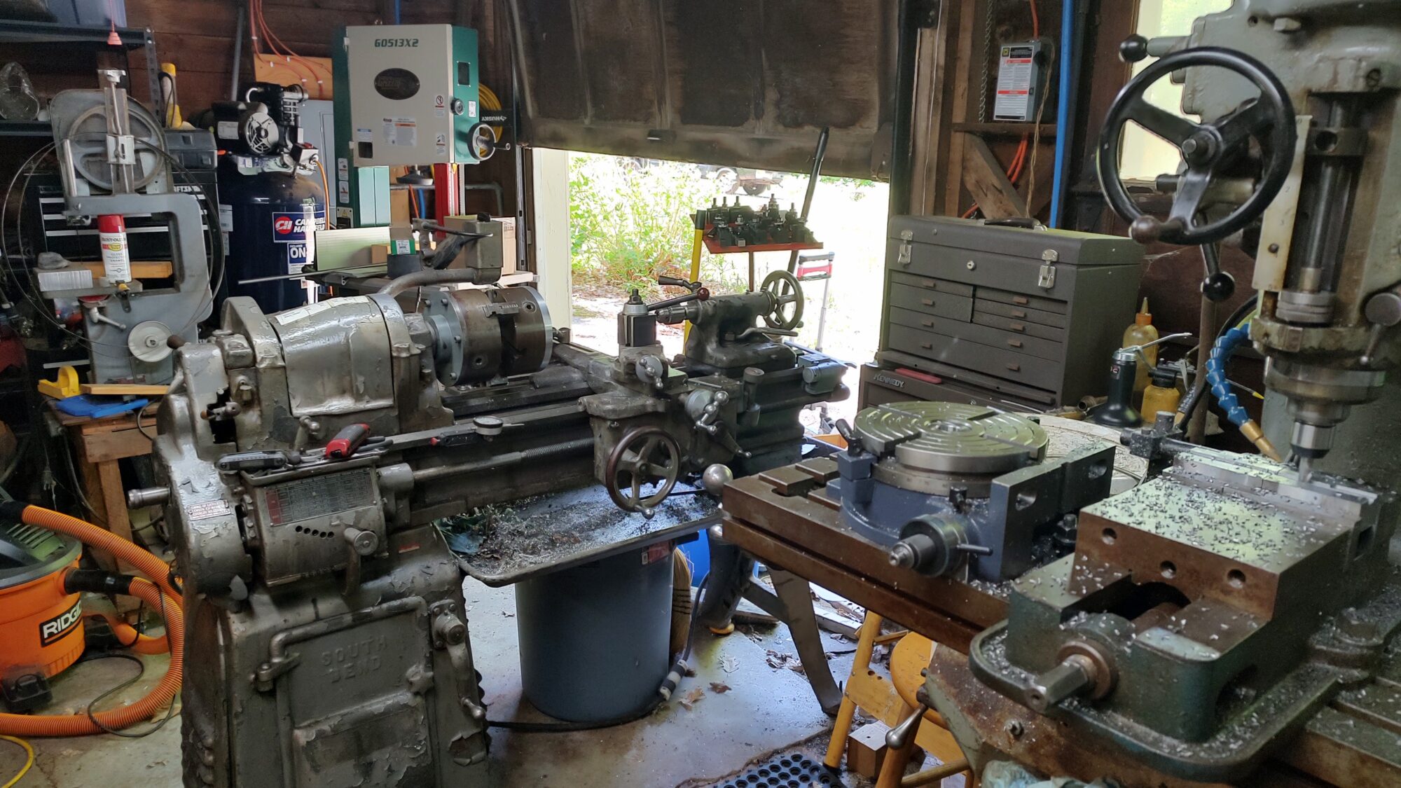
This shows a different view of the shop. On the right, the Bridgeport is cutting a slot in the homemade toolholders.
These 3 are BXA sized, but the front slot is for 1/2″ tools. The key is that the top of the tool is at nearly the same height as if you had a 5/8″ tool in a regular BXA holder. It will be using 1/4-20 set screws for clamping and 3/8-16 for the height adjust.
The red tray over the lathe is shop made. Originally, there would have been a plate to hold collets for the lathe. I did not have the collet chuck, the collet closer nor did I have the tray. I had the post and the ring to hold the draw bar.
A few years ago, I made up this thing. It has three separators to keep the toolholders from sliding down or off. The plate is steel, but the separators are aluminum angle. This was a great improvement and organization system.
The three rows are “right hand turning tools”, “left hand/facing tools”, and boring bars.
I actually have more tools than I have holders, thus the need to make the toolholders. I’m waiting for a dovetail cutter to arrive before I can complete the toolholders.
There is another 12 inches for 6 more toolholders. 4 will be 5/8 slots and 2 will be 3/4 slots.
You can see the rotary table on the mill. I used the rotary table to finish the alignment boss for the chuck. You can see the shiny backing plate attached to the second chuck. Once it was attached to the chuck, I moved both to the lathe to face and turn it to size.
The jaws have been removed from the second chuck to allow it to fit against the jaws.
Yesterday’s progress didn’t feel like that much. I finished the slots in the first three toolholders. I got this picture, so I can break down the chuck in chuck setup. I drilled and tapped the holes in the retaining plate for the rotary table., and I started cutting the groove for the spring washer.
On the rotary table, you can see a small lever pointing to the right. That is the lever to rotate the eccentric to engage or disengage the worm. That disk is a replacement for the original. That is now completed.
Once that was done, I removed the retaining collar, the worm backlash adjust, the eccentric retaining plate.
With that, the eccentric came out with no issues. The worm came out by unscrewing it.
It was here that I realized that I had to cut a groove in the eccentric, not the central. Bummer.
This required changing out the chuck for the four jaw.
Which meant I had to actually clean the four jaw chuck. That went well. It still has 3 tight jaws, but it is much, much better.
Once the four jaw was back together, I realized that the cradle for the 3 jaw doesn’t fit the four jaw. This meant it was a pain in the rump to get it on. It happened.
Then I had to dial in the eccentric so it ran true. What this means is that by moving to opposing jaws, you can move the workpiece. By putting a dial indicator on the boss, you can measure the difference between opposite sides. You then move things until the reading stays the same as you rotate it.
I dialed everything in to within 0.001. For a groove, this is more than good enough.
I then realized I didn’t have a grooving tool. So I ground one.
Just as I started to cut the groove, Something felt off. I think the workpiece slipped in the chuck. I’m not sure that I tightened all the jaws fully.
This means I have to dial it back in again. Not a bit deal, but that is a today job, not a yesterday job.
The only task, after completing the groove, is to cut flats on the worm. This is a slight issue as I do not have any metric 5C collets to hold it.
This means that I will need to get ER40 collet blocks to go with my 5C collet blocks. A cheap set of metric ER40 collets covers nearly the same range as 5C and is pretty cheap.
What I will likely do is to use a pair of matched V-Blocks to hold it and use a square to make both sides parallel.
Again, this is not critical. It just has to be good enough for the crank arm to fit over and to be locked in place by the screw.

seeing all this makes me kinda regret selling my milling mache… then I remember I had it for 5 years and never used it.. and I have a buddy that has both a lathe and a milling machine… very interesting but not funny.
In a way, machine tools are like pickup trucks … if you have ’em, you’ll always have friends who need a couch moved (or a barrel threaded).
That 13″x5′ is a nice lathe; I have it’s mate ready to be restored in my garage. Mine was made in 1934 and sold to the Homelite Corp in Rye, NY. I bought it 25 years ago so when I retired I would have a nice project. Lo and behold, it will need a bit of work to the drive mounting plate as the previous owner somehow cleanly broke the cast iron ears off of where the rod passes through. I bought a locally made Bridgeport-clone from the designer/manufacturer. There was an Italian imigrant who was doing large machine rebuilding for P&W and a few other companies in CT. The owner Mr Morena went to Bridgeport and asked if they’d do a run of his specified mills, they told him to pound sand. Essentially he reverse engineered a Bridgeport, he had the casting done in Taiwan, seasoned them in East Hartford, CT and then machined and built what he needed. Mine has a 10″ wide table and it is 48″ long, the knee is much longer than a Bridgeport. It is a step pulley but there were variable speed models as well. All components, ie. quill, gears, lead screws, pulleys, way wipes are Bridgeport components. It needs a good cleaning and will run for years. Last year, I found a 12″x40″ Gearhead Taiwanese lathe in nice shape, I need to get it lifted up and mounted back on its stands. Too many projects, too much wood to split and stack and limited time. This site is a daily stop and look, this post hit home with your SBL, TY.